The value returned by this pattern is proportional to the angle between a certain ray and the (perturbed) normal at the surface of the object. The range of returned values goes from 0 to 1.
pigment { aoi [ POINT ] }
When no POINT is given, the incident ray of rendering is used. This is not necessarily the ray coming from the camera, it can also be a secondary ray from reflection or refraction effects.
| Note | |
|---|---|
With this option and without reflection and refraction, the range of return values on the visible surfaces goes from 0 to 0.5 since the angle between ray and normal can only be less than 90 degrees | |
When a POINT is specified, the reference ray for measuring the angle will be the ray between this specified point and the intersection point on the object.
| Important | |
|---|---|
This pattern can only be used in situations where the intersection information of the rendering process is available. This applies for usage in pigments, textures and normals but not in media densities or functions. | |
pigment {
  listed FLOAT
  color_map { color_map stuff } } |
  pigment_map { pigment_map stuff } }
}

normal {
  listed FLOAT
  normal_map { normal_map stuff } }
}
This "pattern" is simply a solid pattern, the value of FLOAT is used as the return value of the pattern. This means that the pattern listed at the specified FLOAT value is used as the pattern for the whole object.
This is very useful in having a progression of objects blending from one texture to another, and can also be useful in animating textures.
In this pattern the pattern value is determined by shooting a ray in a certain direction. When this ray hits a specified object it returns 1, if not it returns 0. There are a few options to specify the direction of this ray.
pigment { ... | PROJECTION_PATTERN }
normal { ... | PROJECTION_PATTERN }

PROJECTION_PATTERN:
  projection { PROJECTION_OBJECT PROJECTION_TYPE [BLUR_MODIFIER] }

PROJECTION_OBJECT:
  OBJECT_IDENTIFIER |
  object { ... }

PROJECTION_TYPE:
  point VECTOR |
  parallel VECTOR |
  normal [on|off]

BLUR_MODIFIER:
  blur BLUR_AMOUNT, BLUR_SAMPLES
With point VECTOR specified the rays are shot in direction of this point. When a ray hits the specified object, the value 1 is returned, otherwise 0.
When the keyword parallel is used, a ray is shot from each intersection point in the specified direction. When a ray hits the specified object, the value 1 is returned, otherwise 0.
When the keyword normal is used, a ray direction is determined by the normal vector of the surface. This variation can only be used when the intersection information is available, i.e. in pigments, textures and normals. It does not work in media density and functions.
With the blur option, a number of BLUR_SAMPLES rays is sent, more or less modified spread over an area determined by the specified BLUR_AMOUNT value. The pattern value returned is the percentage of rays that intersect with the object.
| Note | |
|---|---|
When no blur is used the pattern returns either 0 and 1. When used in a pigment only the colors for the values 0 and 1 in the color_map are used. With blur on, the pattern can also return other values. | |
warp {
  displace {
    PATTERN | FUNCTION, COLOR_MAP
    type 0 | 1
  }
}
Displaces the pattern by an amount determined by the PATTERN or FUNCTION and COLOR_MAP at each point.
In type 0, the rgb values of the pigment at each point are used as xyz displacement amounts.
In type 1, the brightness of the pigment color determines the directions and amounts points are pushed.
pigment { noise_pigment { TYPE, MIN_COLOR, MAX_COLOR } }
TYPE:
- 0 - plain color
- 1 - plain monochrome
- 2 - Gaussian color
- 3 - Gaussian monochrome
Produces a "static" effect. This is a pigment, like an image_map, not a pattern. Anti-aliasing tends to mess it up when used in textures, and it is not animation-safe (unless you want an animated static effect). It can be used in an average map to add some noise to a pigment.
This patch introduces support for a new image file format for reading in image_map, image_pattern and other cases. A usual image file stores the color values with 8 bit resolution which means a dynamic range of 255:1. In other words in the dark areas of an image color nuances can only be represented down to 1/255 of the maximum brightness of the image. All darker parts are completely black. High dynamic range images support a wider range of color values than common image files.
The HDR file format supported by MegaPOV is the rgbe format developed by Greg Ward for the RADIANCE software package. It stores the color values in four bytes: three for the red, green and blue color value and one as a common exponent. Further information and image files in this format can be found on:
Syntax for an image map is:
image_map {
  hdr "file.hdr"
  [map_type 7]
}
The new map_type 7 allows correct mapping of the omnidirectional light probes that can be found on Paul Debevec's website and elsewhere.
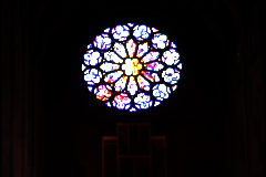
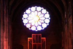
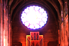
Example 2.9. HDR image example
Varying the ambient finish shows the high dynamic range of the image
camera {
  orthographic
  location <.5,.5,-5>
  right 1*x
  up 1*y
  look_at <.5,.5,0>
}

plane {
  z,0
  pigment {
    image_map { hdr "rosette.hdr" once interpolate 2}
  }
  finish { ambient 1.0 diffuse 0 }
}
HDR images can be most useful for illuminating scenes with a realistic light distribution. Reflections become more realistic and with radiosity you can get a nice appearance of diffuse surfaces as well. A sample scene for this technique can be found in the MegaPOV package. A short tutorial on that matter can be found in Section 4.3.1, “HDRI tutorial”.
POV-Ray™ offers two interpolation methods for images: 2 (bilinear) and 4 (normalized distance). This patch implements a bicubic interpolation as method 3.
In order to obtain the content rendered by some camera as an image_map - without the need for multiple renderings - there is now a new camera_view pigment type introduced in MegaPOV 1.1.
pigment { camera_view{ [CAMERA_ITEMS...] [output OUTPUT_TYPE] } }

OUTPUT_TYPE:
  0 | 1 | 2 | 3 | 4 | 5

  // 0 - classic color output (default)
  // 1 - intersection point components as color components
  // 2 - components of normal vector at intersection point
  // 3 - components of perturbed normal vector
  // 4 - depth (distance between camera location and intersection)
  // 5 - components of uv coordinates at intersection
The scene viewed by this camera is rendered directly within the area <0,0>-<1,1>. Additional output keyword allows other rendering data to be presented (see Section 3.2.1, “Output types for camera_view pigment”).
| Important | |
|---|---|
The camera_view pigment is calculated using structures created after parsing which makes it impossible to evaluate it during parsing of scene. When using the camera_view in a recursive way (image in image) the max_trace_level controls the number of times the image is showed. Raise max_trace_level when at a certain recursion level the image gets the background color. | |